
-
Visit our website www.piratehorizons.com to quickly find download links for the newest versions of our New Horizons mods Beyond New Horizons and Maelstrom New Horizons!-
Join our discord server for regular podcasts/AMA about upcoming and released pirate games (Caribbean Legend, Corsairs Legacy, Ahoy, ERAS 2, etc.):

-
Quick links for Beyond New Horizons
- Download latest version
- Wiki - FAQ - Report bugs here - Bug Tracker on Github -

Quick links for Maelstrom
- Download the latest version of Maelstrom
- Download the latest version of ERAS II - Download the latest version of New Horizons on Maelstrom
-
Join PiratesAhoy! on our social channels:


-

Quick links for PotC: New Horizons
- Download latest version
- Wiki - FAQ - Report bugs here
-

Thanks to YOUR votes, GOG.com now sells:
- Sea Dogs - Sea Dogs: Caribbean Tales
- Sea Dogs: City of Abandoned Ships
Vote now to add Pirates of the Caribbean to the list! -
Quick links for AoP2: Gentlemen of Fortune 2
- Downloads and info
- ModDB Profile
- Forums Archive -
A Pirate Podcast with Interviews
Music, Comedy and all things Pirate!
- Episode Guide - About - Subscribe -
- Twitter - Facebook - iTunes - Android -
- Youtube - Fill the Coffers -
Unity - Modelsetup (MAYA)
- Views Views: 664
- Last updated Last updated:
-
UNITY MODELSETUP (MAYA)
By Wedori // Latest change: 11. October 2014
On the contrary to the former CryEngine (CE) setup, the preparation for Unity is much more easy and in workflow logic.
HIERARCHY
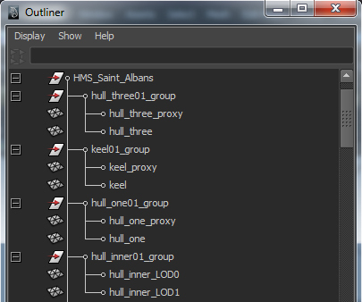
The outliner (hierarchy) need a top node that defines the name of the model. Below the top node you can add more nodes and can collect parts together for its dependency.
In picture 1 you see the top node (models name) "HMS_Saint_Albans". Below the top node follows more nodes with the parts of each submodell. You see for example the keel in one group and the outer and inner hull etc. in own groups.
PICTURE 1:
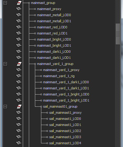
Picture 2 shows an example of dependency of nodes below the top node. You see the "mainmast_group". This one is below the top node "HMS-Saint_Albans". But there are a dependency to the submodels of the mainmast. You see that the YARDS are below the "mainmast_group" node and the sails below the yards. This means: That an rotating yard turn the sail same way and an interacting mast the yards and the sails.
PICTURE 2:
Locaters are invisible helpers, you can place in the modell for special things. For this option you need the case sensitive namings by the programmers (Captain Murphy and Trunks).
In the next points you will find all namings we use actual.
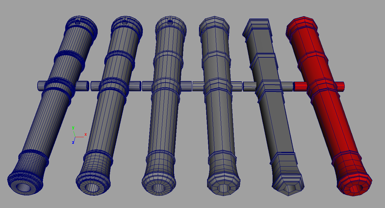
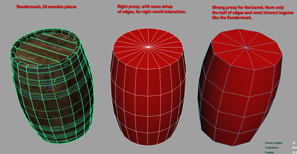
"_proxy": Suffix, tells the engine that the named part in the node is an invisible proxy mesh. This is need because proxy meshes have much less polycount and help the final game to a much better performance. Proxymeshes must be 100% closed meshes! At the picture 3 you see (from left till right) the LOD0 rendermesh, LOD1 till LOD4 and the "_proxy" (the red one).
Note: Meshes without "_proxy" mesh in the node will be physicalized by its rendermesh.
PICTURE 3:
PICTURE 3b:
Please chose the design of the physical proxy wise! When you create a barrel and give the barrel instead of 16 edges only 8, it will never have the final possibility for enviroment interaction. That means, when you have a 16 edge wooden barrel and you give it a 8 edge proxy and then it fall down in the map and must roll down a floor then it wont roll. A guns barrel cant roll, here you have another situation. Understand the sense of the mesh.
Or another example: The small ship doors are too small to pass it with the character. Here you can give the physical proxy much more space to let the player pass.
So please chose the design of the proxy ever to the sense of the rendermesh!
In short words: Physical proxys must relieve the engine. So you doesnt need to use a 30.000 polygon gun barrel as proxy BUT you must setup the proxy to hold its sense for the rendermesh (example wooden barrel).
The next picture shows you the example at the wooden barrels:
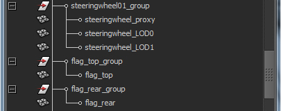
"_LOD0": Suffix, is the naming for the rendermesh when the part use LODs. The next LOD-stages are "_LOD1", "_LOD2", "_LOD3"... till 6. Parts without LODs (only small rendermeshes) didnt need the "LOD0". You can chose by yourself if you type it or not. Only the LOD-engine need for all LOD stages the "LOD0" naming in rendermesh. On the picture you see the node "steeringweel01_group". You see the nodes proxy and an rendermesh "_LOD0" with one LOD-stage "_LOD1". The two nodes below (flag_top_group & flag_rear_group) have no proxys and and no LODs. It is not wrong to name "flag_top" shape to "flag_top_LOD0" but it havnt a LOD, so its OK with just the name.
In picture 3 above you see LOD examples and in picture 4 the outliner hierarchy of placement in the node.
PICTURE 4:
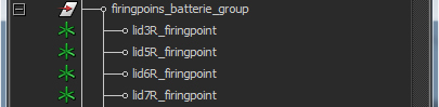
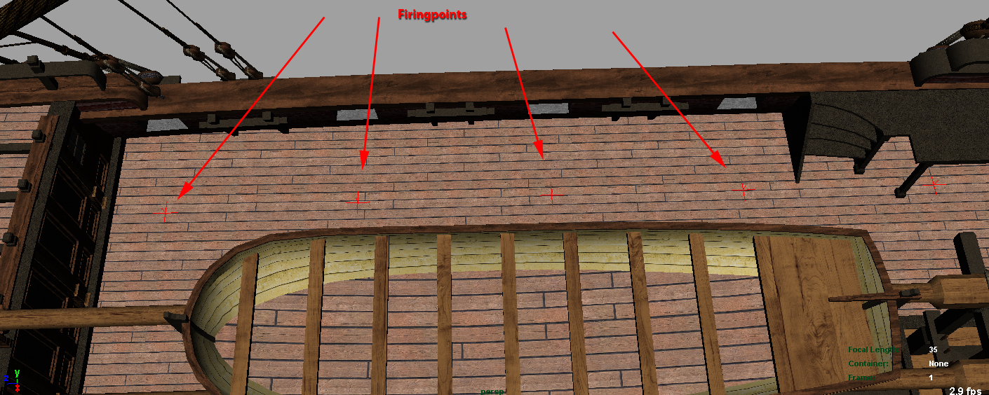
"_firingpoint": Suffix, is the locater (invisible helper) position for the gun position on deck. I have named the "_firingpoint"s in designation to the gunports. Picture 5 shows as example 4 "_firingpoint"s in the batterie deck node.
Please note, that this helpers define the stored gun. The best way is to check guns length and set the helper to the position, the gun is right inside the ship. Attention: The helper read the guns top node pivot!
PICTURE 5:
PICTURE 5b:
"buoyancy_mesh": MESH-NAMING, is the whole name of the needed second proxy for ships. Only ships need this proxy, who tell the engine its water interaction. On picture 6 you see how this is meant. Picture 7 & 8 shows the 3D side of the buoyancy mesh.
This mesh is below the top node.
PICTURE 6:
PICTURE 7: You see the batterie gun ports closed. This is important in reason of high waves interaction. Like written above: The mesh must be 100% closed like the physical proxys!
PICTURE 8:
1. SHIP SETUP
For better overview over the very big ships hierarchy I have split it into 3 views:
LEFT: The complete open one
MIDDLE: All nodes visible
RIGHT: Only Top node open
Dont fear the size of the hierarchy. A ship must be for optimal performance reasons setup wise.
Please study the hierarchy and youll understand what I have done.
PICTURE 9:
An big advantage of the Unitysetup is, that we can hold all parts of the ship in one file. The gunports too.
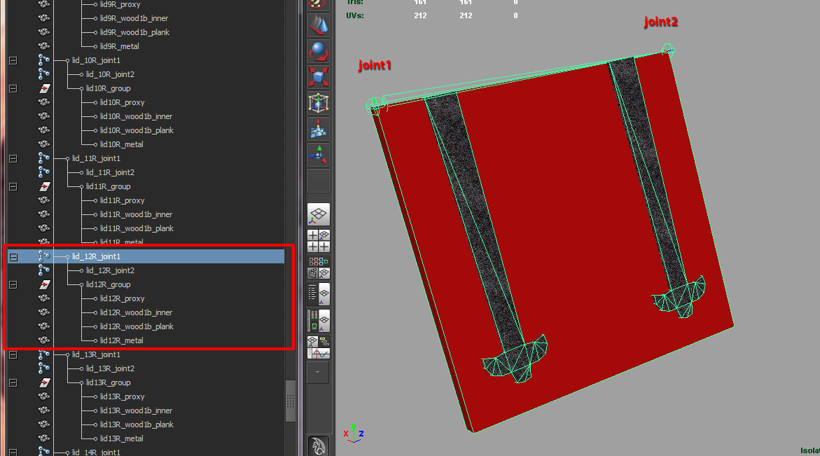
Here comes an important information about the joint-technique, we used in CE too. Two joints resulting in a bone with joint orient pivots. This means, that a bone align its joint pivots the the same axis. The very big advantage is, that we can place a node below the second joint and it will get its pivot orientation. This is much important when we want to define special rotation axis, like the rudder or gunport lids.
The next picture shows the setup of a gun port lid. The bone placed along the lids rotation axis at the front edge of the lid (rotation center).
PICTURE 9b:
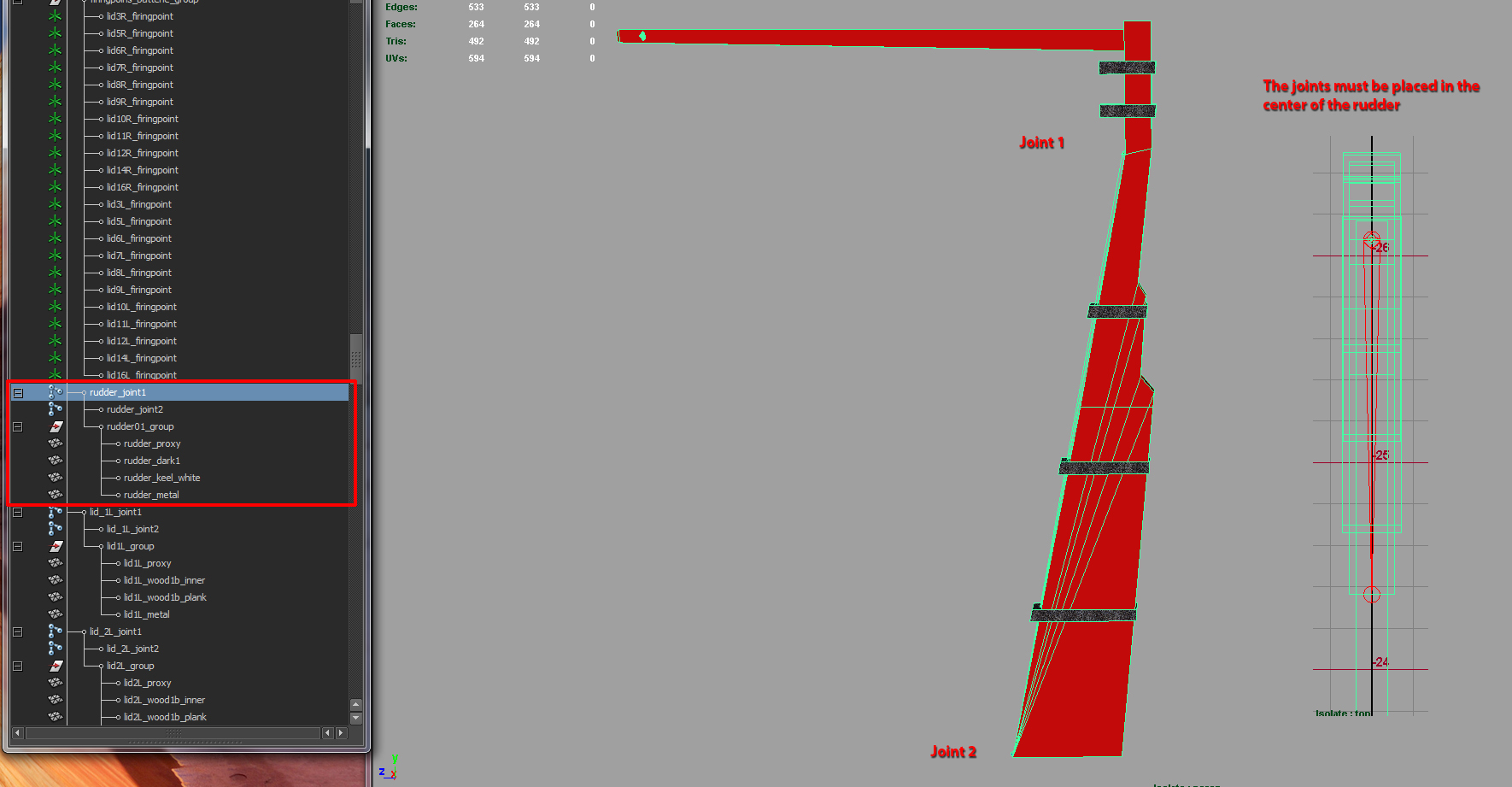
And here we have the example for the rudder. The joints are placed in the center of the mesh and along rudders rotation axis.
PICTURE 9c:
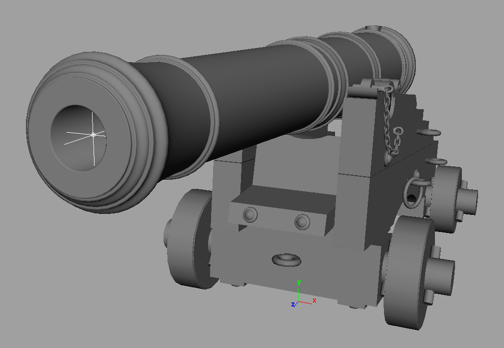
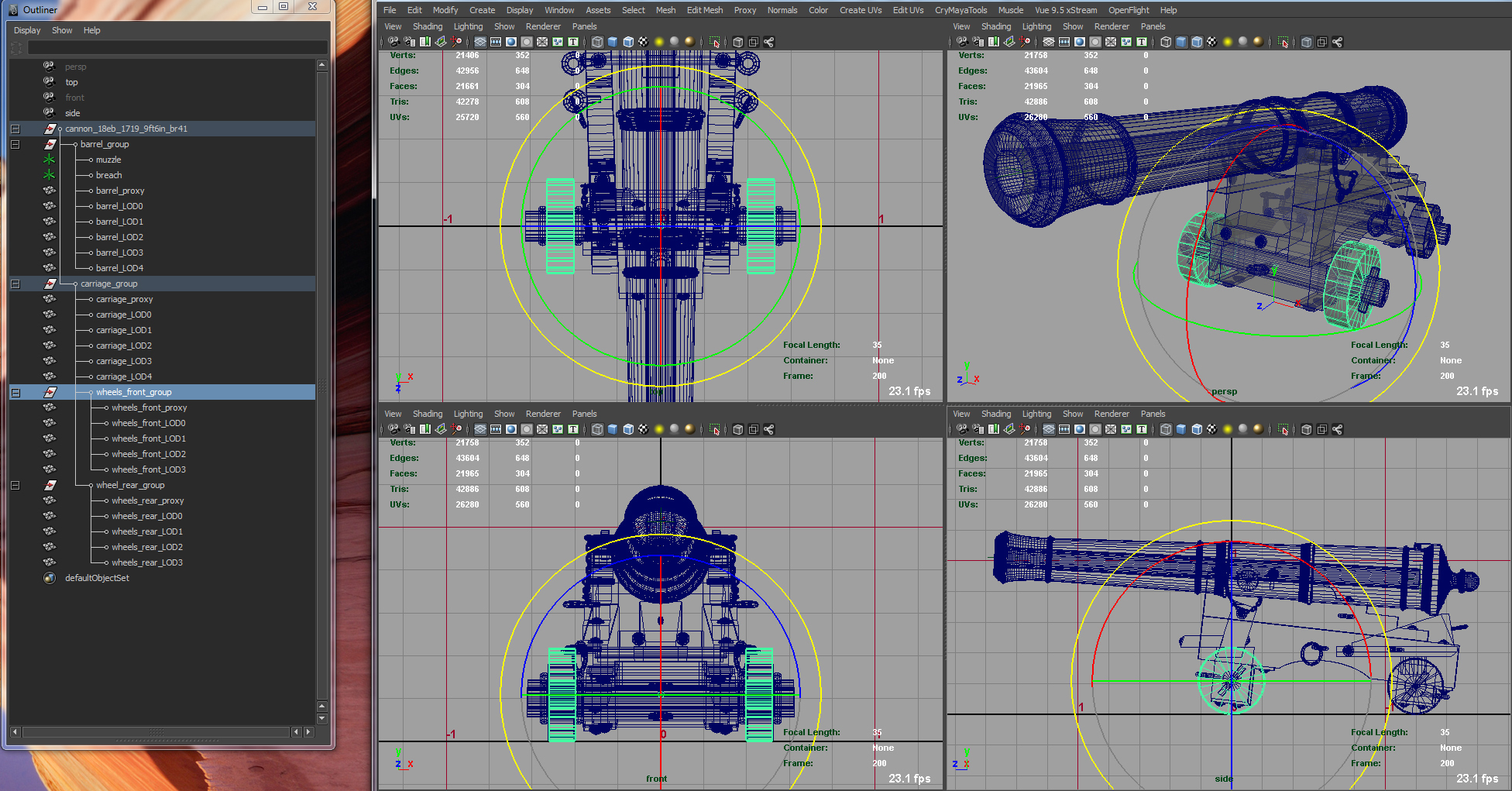
2. GUN SETUP
The gun setup is an very easy thing too. Like learned above, the top node is the name of the gun and below you find the part nodes and its dependency hierarchic submodells.
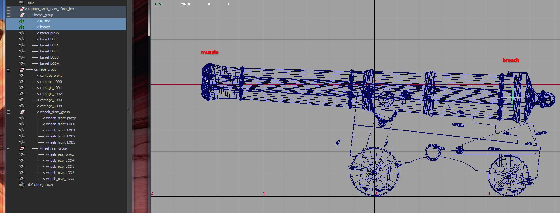
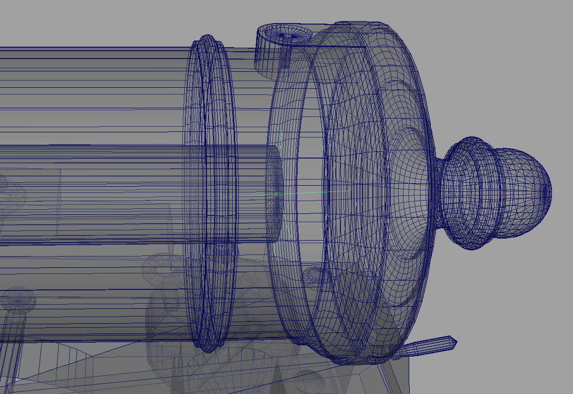
Please note the both important locaters (helpers) for guns: "muzzle" & "breach". This two tell the engine the angle of the guns bore!
"muzzle" is at the front of the bore (center position of bore hole at the front) and
"breach" at the end of the bore, same center of the bore. See picture 11 till 11c!
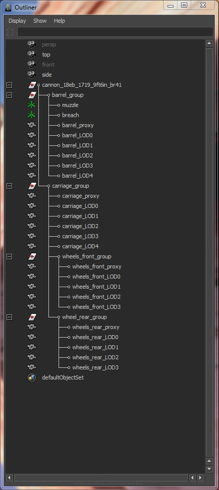
At picture 10 you see the whole hierarchy of a gun. Please note the dependency of the wheel nodes below the carriage node.
The center of the wheel nodes are at the positon of the rotation center! See picture 12!
PICTURE 10:
PICTURE 11:
PICTURE 11b:
PICTURE 11c: X-ray of the breach at the end of the bore
PICTURE 12:
to be continued...
-
