• New Horizons on Maelstrom
    Maelstrom New Horizons


    Visit our website www.piratehorizons.com to quickly find download links for the newest versions of our New Horizons mods Beyond New Horizons and Maelstrom New Horizons!

Victorian Factory

Robert Nutter

Serving Victoria
3D Artist
QA Tester
Provisional
Storm Modder
Hello all!

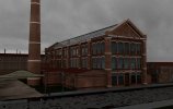
I couldn't help but notice that this section of the forums is a little dead. So, seeing as I learnt pretty much all my foundation modelling skills from this community, it only seems right to share a personal project I've been working on. This hasn't been for any client, but I've had a lack of industrial work and it seems a shame as I LOVE these old buildings so much. So to fill a gap in my portfolio, I made this. Taken around 20-25 hours so far so it's definitely a speed over quality project, though I don't think it's turned out *that* bad. I'm now animating it and along with a trusted composer from my film days, intend on creating a cinematic short to complement the stills.

This is significant, as it's my last project for which I'm using a standard renderer. After this I'm switching to V-Ray.

Anyway, I'd DIE for some comments; good or bad! :doff

Excerpt from my WIP portfolio:
--------------------------------------
Type: Industrial (Manufacturing)
Ownership: Major Lockworks
Present status: Fictional
Location: West Midlands, England
Period: Late 19th Century
Style: Victorian Classicist
Construction: Pressed Brick (Imperial Red/Staffordshire Blue), limestone (aesthetic), riveted wrought iron (structural, roofing), Birmingham terracotta (dentils/ledges)
Extra features: Canal with waterside steam crane and ox walk
Modelled & textured in Cinema 4D. Stills & Video rendered using Cinema 4D's Physical Engine. All assets available on request.


Some elevations:
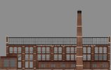
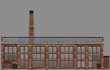
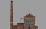
Side 2 Elevation.jpg Side 1 Elevation.jpg Front Elevation.jpg

Playing with different lighting to see which mood works best (rough renders):

Still.jpg 13 Overcast.jpg 13 Night.jpg

I also modelled a lot of auxiliary props for this, including a highly accurate Drey, Steam Crane, Sack Trolley and Canal (not in images).
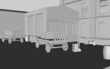
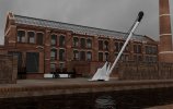
444.jpg Untitled.jpg

Interior of the main machine shop is also modelled to an extent, though I'm not entirely happy with it. I was going to build a Steam Engine and lathe benches but don't have the time to justify doing it. I've done some drive shafts etc though so it looks ok enough. I have some nice volumetric lighting lined up, which should really give the building some character from the inside! Hopefully if anyone's interested, I can post some interior renders up once I get them done.

Here is the boardroom (very early render so excuse the poor GI going on...)
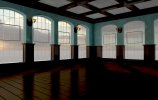
4 Boardroom.jpg

And finally, some earlier pics of the structure. This took AGES to do, as I had to create all the girders and ironwork from scratch which meant a tonne of research into structural engineering of the period which is surprisingly awkward. I know it seems silly to waste time doing this, but in my experience thus far, it's the kind of thing clients notice first.

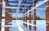
Screen Shot 2016-09-10 at 11.26.26.jpgScreen Shot 2016-09-10 at 11.44.09.jpg

Overall I'm a little disappointed with my textures, but I havn't had much time to really take a proper stab at them so they'll likely remain as they are. I also know these renders are by no means whatsoever 'great', as I'm still working on lighting and settings; but texturing is pretty much done as is modelling, so any input on any of this would be hugely appreciated. I'll also credit anyone whose advice I use in my portfolio :pirate41:

(Oh and here's a sneaky example of some of my practice work I did months ago when I was still active here, using some of the tips @Armada taught me. Just to show how grateful I am. I think this might even pre-date Hampden Estate by a few days...)
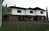
14 Front Edited.jpg
 
Last edited:
Well, I know squat about modeling, but I work in construction and have done some structural engineering and I think your architecture looks good for the most part. I think the vertical post's of the interior look slightly undersized for all the I-beams they're carrying. The ones from the roof to the I-beam look good as the majority of the roofs weight is shed to the outer walls by your nicely done trusses, but the ones under the I-beams running the length of the building could be enlarged, or possibly doubled (add one in-between each set) though that may get a little busy looking and probably interfere with interior work you've already done.

I like the cloudy day lighting myself. It has a pale industrial feel to it that seems to muddy the texture quality as opposed to the night-time lighting that seems to be intentionally hiding the texture quality. Although I do like the shady, criminal underworld, down by the docks atmosphere the night lighting has. Again, I know nothing about modelling so feel free to completely disregard my amateur analysis.:wp
 
@Keel-haul Kelley , to be honest you've made my day; and I mean that :yes

I agree now you've drawn my attention to it, the vertical supports are a little underwhelming considering the weight they're bearing; i'll give them a few more inches I think :)

More I-beams is never a bad thing! I was tempted to add more between to fill the gaps but ended up not doing it as I felt the curtain walls wouldn't realistically be expected to support anything as direct, but I take your word over mine anyday so you've confirmed something else for me there! Tbh all I've done for the interior is some drive shafts, railings etc and stairs; the ironwork was always the most important part for me. So plenty of room!

A lot of the roof support was gathered from multiple sources so it was kind of a case of combining several different techniques. Entirely glass roofing like this was so rare on large industrial buildings in that period that I felt like I was shooting into the dark at times. The trusses were mostly a judgement call to be honest; my father's an engineer and I always remember him telling me to 'triangulate' in my lego or cardboard models if I wanted strength. So I had a look at some Victorian railway stations to see how they did it and sure enough realized it was what I needed to do!

The overcast is my favourite, too. The only thing is, from a technical point of view some could argue the sunny one is better as it highlights the textures and objects more. But yeah night is too dark for anything short of a Noir thriller, and overcast just has the right 'feel'. :) I also think the texturing looks best in that light :cheeky

Please, comment away! I'm very much the amateur in this realm and want/need to learn everything I can about structural engineering. :onya Afterall, you can't model what you don't know!

EDIT: I just realized something important which is not clear from these images; the layout is actually stacking 'mezzanines'inside the machine shop itself, hence the large gap in the middle. I decided to do this and sacrifice floor space as it would allow for maximum light to penetrate the lowest floor (hence the glass roof). Lathes and machines would be on the 2nd floor, meaning it was important to give the hand crafters as much light as possible on the lower ones. This is probably a little inaccurate, but there never was a lockworks of this scale made for Thomas Worrall so it's a 'what if?'. Its actually very open plan for a Victorian building!
 
Last edited:
I know nothing about structural engineering, but from a modelling perspective, I'd say your factory looks very well-built. :thumbs1
Of course, what everyone really wants to know is: how many polys? :p

I like your renders with the different lighting, and I have to agree the overcast one looks best (daytime version looks a bit 'flat', and the sky texture lets it down).
In all of them, I initially thought there were holes in the road in front of the factory, but on closer inspection, I can see they're reflections showing in still water. This could do with some distortion to break up the 'perfect' reflections, or maybe just less water on the road.
Your other practice work looks good too! I'm curious to know which tips of mine were applied to that scene. :read
 
I know nothing about structural engineering, but from a modelling perspective, I'd say your factory looks very well-built. :thumbs1
Of course, what everyone really wants to know is: how many polys? :p

Thanks! :) I'm happy with how the modelling went with this, as I did it in record time for me (under a week for everything, alongside doing other larger projects).

Poly wise...thing is, I envisaged doing a lot of super close up shots of stuff like the Drey and ironwork. So even a rivet is 8 polys heavy (I kid you not..they are individually modelled :no), so overall including stuff like the street lamps and cobbled road (which btw ISN'T a texture... :modding) it comes to around 3million. Again, though, this is for my own visualisation purposes and not game design so I can *kinda* get away with it as it's only stills and 1080p frame renders I'm doing. Couldn't really afford to go back in and optimise it so it's stuck this way. I could probably have bought it down to around 4-500k overall, though, if I'd had a little more time :yes

I like your renders with the different lighting, and I have to agree the overcast one looks best (daytime version looks a bit 'flat', and the sky texture lets it down).
In all of them, I initially thought there were holes in the road in front of the factory, but on closer inspection, I can see they're reflections showing in still water. This could do with some distortion to break up the 'perfect' reflections, or maybe just less water on the road.

This is handy to know, as I have yet to do the vast majority of renders and it's good to have a lighting type which I'm not the only one to like! As for the water, I had tried with slight ripples but I kind of wanted this to retain a 'industrial' atmosphere, so almost like that standing water is oil saturated thus thicker/dirtier. You are right, though, I need to enhance the reflections somehow as they can look like holes from some angles. The whole road is humped in the middle, so it's just a flat poly with the texture applied anyway.

I know the sky HDRI is shoddy; I had a better one but was scared of copyright....should probably take my own :D


Your other practice work looks good too! I'm curious to know which tips of mine were applied to that scene. :read

It was no one thing, really. When we were working on Dundas together I already knew I wanted to start taking archviz more seriously, but I found it hard to be critical of what I'd done as I was misinformed to begin with. The many extremly helpful changes we went through with Dundas gave me the confidence, more than anything, to be critical of my own stuff and not scared of trying it out for fear of 'ruining' the mesh. Beyond this, though, you helped me a LOT with texturing and wrapping my head round how to use it, as well as the importance of optimisation (that house is only 150k polys overall; excluding the trees and grass, of course). But yeah more than anything it was a mindset you helped me get into (well you and Pieter, but from a strictly modelling perspective, it was more you) which is basically that I shouldn't be scared of trying stuff. Your approaches to Bellona, for instance, like doing the lofting differently (I used lofting for lots of small details on that house, ie door handles, guttering etc) and how you cut out those gun ports, inspired me to find ways of doing stuff I wouldn't have learnt otherwise. :drunkSo I should probably have said 'things' and not 'tips', so much ;)
 
Last edited:
Glad it was helpful. :onya

I think if you want to add more beams from the curtain wall to the central I-beams there should be another horizontal beam running between the brick columns for it to meet. That would carry the load out to the brick columns so it wouldn't be coming down in the center of the curtain wall. I had thought about suggesting moving the beams you have there already to be level with the I-beams but it looks like those are the sill plates for the windows.

(Edit)The edge of your floor along the curtain walls would need something to sit on anyways

I don't know much about Victorian era industrial architecture and I'm certainly not "an" engineer, but I have learned and understand load path pretty well. I'm primarily a carpenter so it helps to understand what the weight of a structure is doing so as not to have it fall on my head when a client wants me to remove a load bearing wall. I was fortunate to have a couple friends ask me to design and build their homes in the past few years so I studied up on structural engineering so I could do it for them safely.

I had also mistaken the puddles for holes at first.
 
Glad it was helpful. :onya

I think if you want to add more beams from the curtain wall to the central I-beams there should be another horizontal beam running between the brick columns for it to meet. That would carry the load out to the brick columns so it wouldn't be coming down in the center of the curtain wall. I had thought about suggesting moving the beams you have there already to be level with the I-beams but it looks like those are the sill plates for the windows.

Once again you're absolutly correct; I had considered that the columns needed some added help. I added the sill plates mostly for aesthetics (I love using dentils XD) but also to hint that there was some structural rigidity under there. I don't actually know why i ended up not doing that, must be one of those things I simply forgot about. Bad Rob! :wp

(Edit)The edge of your floor along the curtain walls would need something to sit on anyways

I consciously avoided spending too much time on details for the lower parts of the building, as it's not something there will be any renders of. But for purposes of realism you're absolutly right that I should've done that! :pirate41:

I don't know much about Victorian era industrial architecture and I'm certainly not "an" engineer, but I have learned and understand load path pretty well. I'm primarily a carpenter so it helps to understand what the weight of a structure is doing so as not to have it fall on my head when a client wants me to remove a load bearing wall. I was fortunate to have a couple friends ask me to design and build their homes in the past few years so I studied up on structural engineering so I could do it for them safely.

I had also mistaken the puddles for holes at first.

I really respect your views on the subject as all your points make perfect sense; thanks! May I ask, what approach did you take on studying the subject? As I really need to bone up on structural engineering but don't have a singular clue where to start :read

Oh I've added some ripples now :pirateraft
 
Last edited:
Intro Load Path - Documents - Online Powerpoint Presentation and Document Sharing - DocFoc.com (Edit: sorry 1st link I posted was only a preview think this is free to view and download)

This is a really good introduction to it. It teaches the basics and gives some good references for getting into more advanced architecture. It's focused on wooden structures but the same principles apply to any building, though different materials have different strengths and weaknesses. Such as steel or iron I-beams being able to span much longer distances than wooden beams. For an artist, I think, it should help you understand why and where different types of support are needed.

I do really like the trusses with the cross-braced beams running under them and the open mezzanine floor plan. I had meant the upper floors when I mentioned support for the edge of the floor's though it would make sense that it would be hidden in the brick of the curtain wall. I guess I was looking at it as a building under construction and not what would be visible when it was done. :shrug
 
Last edited:
Wow thanks that's just what I've been after! :thumbs1 Some good solid information in here...:bow

The 'box' going around near the top of the walls is my idea of hiding the structure. Without it, there'd be a skeleton of supports visible outlining the top of the walls and the edges of the floors. I should probably have added some 'naked' ones for the first floor, though as you're right; it does look kind of like the columns would flex in the middle. But as you say, the walls do hide a lot of ironwork.
 
If your really going for accuracy there is a free program called Beam Calculator that you can use to check if your beams are the correct size. Need to research the weight of your materials then use the info you'll learn in Load Path to identify where each square foot of weight is going, add it all up and plug that into the calculator. That's basically real deal engineering out a building so may be a little overkill for what your doing.

Looking forward to seeing some of those interior scenes your doing. And I promise not to get all building inspector on them:keith
 
Definitely a little overkill for this but no less important! I have some projects coming up which I'll definitely be learning/using that for :onya Sounds handy.

I'll be sure to, though I actually got the interior done a few weeks ago: I'm just sorting out lighting as that glass roof makes realistically rendering it out surprisingly tricky. :rumgone
 
Hi all!

Just thought I'd update you on this project.

This has just gone live on my folio. As only the second project on there, the portfolio is overall very unimpressive; but I'm having trouble getting other projects ready to put on there and thought at least having this one up is better than nothing!

I havn't managed to get enough elevation/technical views rendered at this point to make the promised '2D elevations' section of the carbonmade page worth doing right now; mostly because I have a huge render queue to get through at the moment :modding

Also, let me know if you run into issues loading both the Behance and Carbonmade pages :onya ; and of course any thoughts which may come to mind about either the layout or the renders themselves; it all helps :) I'm still trying to establish not only my online workflow/style but also what I show off and what I don't at this point, so feedback is crucial.

In case you missed that first one, here's the link again!
 
Last edited:
Back
Top